
The following report was created April 10, 2015 in response to a very sub par Wi-Fi system operating at the Dunkin Donuts Center. The company responsible for engineering and installing the system hired several “experts” to come in and analyze the problem, but as of April 15th, 2015 the system had failed to deliver during a single event for almost a year. In order to try and get a solution to the problem, one of CRT & Associates’ software engineers took the Ruckus online, high density Wi-Fi courses which led to this report.
All,
The images Mark sent me are very helpful for showing both what we are aiming for and where we still have problems.
Note: Much of the information I will provide and more can be found at http://www.metageek.com You will even find a discussion there about WiFi / ZigBee interference: https://support.metageek.com/hc/en-us/articles/203845040-ZigBee-and-Wi-Fi-Coexistence
Before we look at the images, I want to discuss channel selection. I have often mentioned that channels 1, 6, 11 are non-overlapping channels and the only channels we should consider using. Let me explain why:
WiFi communications is a spread spectrum technology. Originally developed as a secure battle field communications system, its ability to “work around” noise and interference brought it quickly into the main stream. Each channel is 22 MHz wide. (In many analyzers, channels are shown as sinusoidal curves, but in reality they are more square wave shaped) When you are connected and communicating with the AP, you are doing so on constantly changing frequencies within that 20 MHz range. This allows the system to avoid interference from a single frequency source. Unfortunately, the entire North American 2.4 spectrum is only 50 MHz (center freq. – center freq.) Thus we only have 3 channels that don’t overlap. Why is this important? When we are communicating with an AP a sophisticated algorithm is used to manage the frequency hoping among all the users connected. If two APs are both using part of the same 22 MHz spectrum slice they will inevitably try to communicate on the same frequency at the same time, creating a collision and the need for a re-transmission. We avoid this by using only non-overlapping channels.
If two APs are on the same channel, the APs will negotiate a sharing plan to make sure they operate as efficiently as possible, HOWEVER, what’s the point in it? You gain nothing, no additional users or speed gain over a single AP. In fact the extra negotiation between the APs makes the net gain negative.
I like analogies, so I’ll use one here: Think of a Wi-Fi communications like a news/press conference. The subject holding the news conference is the Wi-Fi AP. He or she chooses someone in the audience to ask a question then they answer it, but only one at a time. As soon as it is clear the question is answered, everyone “negotiates/fights” to ask the next question and the cycle repeats. Now suppose a second subject is added, a second podium if you will. Now the two subjects (APs) have to negotiate who is going to take the next question, before someone can be selected to ask the next question. The room where our press conference is being held represents one of the 3 non-overlapping channels, 1, 6, 11 (in the 2.4 GHz band). If we open a second room up and move the 2nd subject into that room, now both subjects can take and answer questions independently. They are now on different channels.
So now there is probably a question: Our building has lots of APs on the same channel, how does anyone build a great system? There are multiple variables that you can tune within an enterprise class system, and here is one: Each AP can be told to ignore all radiant energy below a certain threshold. This is so important, let me say it another way: Each AP can be set to ignore everything it sees below a certain energy level (-dBm). In additional it can be told not to associate with a device unless a minimum signal strength (S/N ratio) can be maintained. Another is the noise floor. Ap’s can be taught to ignore all signals below a minimum threshold. But there one thing not related to AP settings that will make all the difference, AP isolation. Keep reading.
With all this information lets look at Mark’s first image (live data collected during a live event. Location is IDed as “players”):
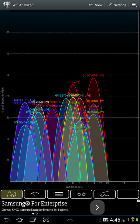
The first thing we notice is there are only two predominate signals, one GBL (ch 11) and one DDC (ch 8). This is good, however they overlap slightly.
Next, the signal strength is about -53dBm for GBL, Very good (-67 is all that’s required for video streaming), Remember smaller negative numbers are bigger values.
Unfortunately that’s where the good news ends. For now let’s say we need both DDC event (what is this? A rouge network set up by an employee?) and Go Beyond Live SSIDs. This creates extra overhead and slows down both networks and you cannot roam between them, but for now let’s say we need both. Knowing that you can tell an AP to ignore signals below a certain threshold, where would you draw that line, given the above graph? Here’s where I would:
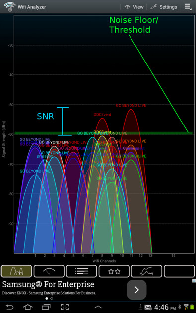
The problem with this is that it gives us only a, roughly, 7 dBm SNR (-60 – -53). Way below acceptable. We should be shooting for a minimum 15 dBm SNR and ideally somewhere above 20 dBm. Keep in mind that these curves are fluid and move up and down during any given time frame, so some margin of error also has to be provided. We might be able to move the AP floor down to around -66 (the next GBL on the ch 11) but we would get a boat load of overlapping from all the stuff on ch 9.
I don’t know where this data was collected (players), but the signal level is fine, just not enough isolation from the other APs.
Mark’s image #2 (Zamboni):
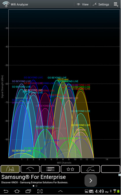
By now, you should be able to see all the problems with this one.
If you were a mobile device, and, assuming these curves move a minimum of +/- 3dBm from where they are right now, which AP would you associate with? You wouldn’t
If you were the AP controller, where would you tell each AP it’s noise floor should be? You couldn’t or if you did it would equal the signal power, about -60dBm.
The system is unusable at this location. Each time there is a minimum shift in power levels the mobile device disassociates and re-associates with a new AP. The “strongest” GBL at ch 7, has a strong DDC right on top of it at ch 8 and a GBL of almost equal strength also at ch 8. This location is truly and totally FUBAR.
Lets take a look at the 5 GHz side of the house:
First, players.
Here a tip for everyone, since the 5 GHz band is much wider, the analyzer has a sliding view. The tab at the top can be slid left and right to provide views of the rest of the band.
As before, and not surprising, not terrible. At the AP most devices would associate with, GBL at ch 40 (above image) about -63 dBm, only one co-located channel, another GBL at about -75 dBm. So again, not enough SNR for a solid connection, again not enough isolation. Also think about this: If the signal level of GBL at ch 40 fell just 7 dBm, the device might try re-associating with a stronger AP at 48 or 52, and that is not a good thing at all. We want people to get and keep an AP unless they are on the move.
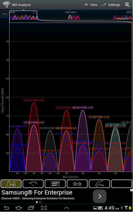
5 GHz Zamboni:
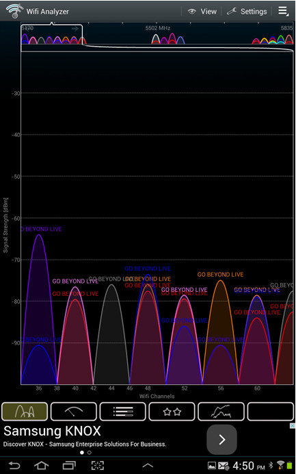
Surprise!
At ch 36…Really pretty darn good. Enough signal for video, around -63dBm, and with no overlapping channels you could set the noise floor at -90dBm and get a SNR of around 25 dBm, really good.
The only issue that would need to be looked at here is “heat” or utilization. How many people are using this AP on ch 36, and how heavy is their use.
Ch 36 is well isolated at this location.
Basically, this is what you want all location in the building to look like in the 5 GHz band. Different channels of course, but you can see exactly where your device will associate, and you can see it should be pretty good quality.
It does look like there are other AP with as high or nearly as high signal further down the band (5502) that we would need to address to make sure our mobile device doesn’t spend its time jumping back and forth between APs, but this is how we want it to look given this slice of the 5 GHz band.
So now you should be getting a good idea of what a properly installed system will look like on your Analyzer. As you walk around the DDC with the Analyzer running you should see the curves rise and fall with only one cure high above the others at any one location. There will be boundaries where you will have two or three peaks (shouldn’t be more than that though, all on different channels). At those boundaries the AP and device will decide if and when to drop one AP in favor of another.
You should see now that this is one gigantic dance to maximize SNR and minimize channel overlap. Raising the power on an AP increases it’s SNR, but also increases channel overlap on lots of other APs. At this time, and for the locations Mark got data for, it appears the power level for the AP’s is correct. They just need (a lot) better isolation. This problem is known a CCI (Co-Channel Interference)
Jerry.
Update: Dec. 12, 2017
Unfortunately, the information in this report went unheeded and the system was abandoned, as far as we know. Ironically, the DDC’s building construction provided an opportunity to isolate AP’s almost perfectly. The large, exposed, metal beams supporting the roof could have provided an excellent way for the AP’s to be shielded one from another.